Search This Blog

Monday, 16 November 2015

4 Essential Features of Transformer On-Load Tap Changer (OLTC)


4 Essential Features of Transformer On-Load Tap Changer


Done on the HV winding

On-load tap changers (or circuit tap changers), as the name suggests, permit tap changing and hence voltage regulation with the transformer on-load. Tap changing is usually done on the HV winding for two reasons:
  1. Because the currents are lower, the tap changer contacts, leads, etc., can be smaller.
  2. As the HV winding is wound outside the LV winding, it is easier to get the tapping connections out to the tap changer.
Figure 1 below shows the connections for an on-load tap changer that operates on the HV winding of the transformer.
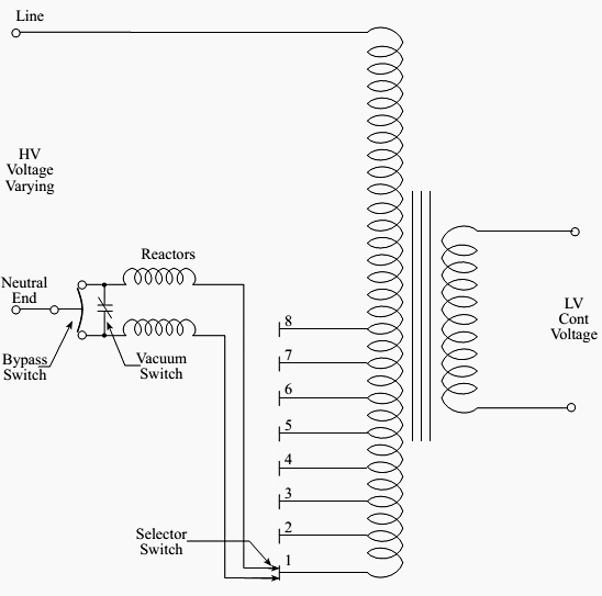
On-Load Tap Changer
Figure 1 – On-Load Tap Changer
The tap changer has four essential features:

1. Selector Switches

These switches select the physical tap position on the transformer winding and, because of their construction, cannot and must not make or break the load current.

2. Reactors

The load current must never be interrupted during a tap change.
Therefore, during each tap change, there is an interval where two voltage taps are spanned. Reactors (inductors) are used in the circuit to increase the impedance of the selector circuit and limit the amount of current circulating due to this voltage difference. Under normal load conditions, equal load current flows in both halves of the reactor windings and the fluxes balance out giving no resultant flux in the core.
During the tap change, the selector switches are selected to different taps (see Figure 2) and a circulating current will flow in the reactor circuit. This circulating current will create a flux and the resulting inductive reactance will limit the flow of circulating current.

3. Vacuum Switch

This device performs the duty of a circuit breaker that makes and breaks current during the tap changing sequence.

4. Bypass Switch

This switch operates during the tap changing sequence but, at no time, does it make or break load current, though it does make before break each connection.
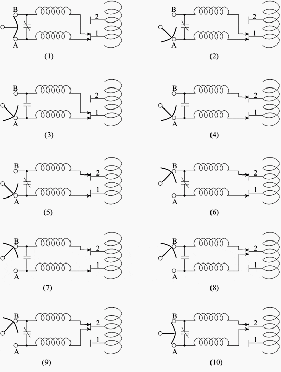
An example of the tap changing sequence is detailed in Figure 2 (diagrams 1 through 10). Table 1 describes the sequence of operations for the tap changer of Figure 2 to change from tap 1 to tap 2. Changing to any other tap position is done similarly with the selector switch always moving sequentially (i.e., it is impossible to go from tap 1 to tap 3 directly, the order must be tap 1, tap 2, then tap 3).

The sequence of operation is mechanically linked, orinterlocked, to ensure that all contacts always operate in their correct order. Any failure of the operating mechanism can result in severe damage to the transformers and tap changers.
Table 1 – Description of Tap Changing Sequence for Figure 1
No. Details of Tap-Changer operation
1Present position – tap changer selected to tap 1, bypass switch in, A + B, home position.
2Bypass switch selects lower circuit arm.
3Vacuum switch opens, removing load current from upper circuit arm freeing one half of selector switch for move.
4As there is no load current on upper arm of selector switch, it moves to tap 2.
5Vacuum switch closes – both selector switches onload, circulating current is limited by reactors.
6Bypass switch selects upper arm circuit arm. No arcing occurs as vacuum switch is closed and in parallel.
7Vacuum switch opens, removing load current from lower circuit arm, freeing lower selector switch for move.
8As there is no load current on lower arm of selector switch, it moves to tap 2.
9Vacuum switch closes – both selector switches onload, in parallel, on tap 2.
10With vacuum switch closed and selector switch on a single tap, the bypass switch can now return to its home position. Both reactor circuits stay normally in parallel. The tap change is now complete.
Illustration of an On-Load Change Operation
Figure 2 – Illustration of an On-Load Change Operation

The previous example describes one type of on-load tap changer. There are several other types inuse however, which may differ significantly from the type described.
Difference Between ELCB, RCB and RCD Circuit Breakers

ELCB: Earth Leakage Circuit Breaker

ELCB stands for “Earth Leakage Circuit Breaker” and it is used for protecting a person from electric shock and injury. The needs of these devices arise because of the number increasing in injuries as well as deaths because of electric shock. This device is invented almost 50 years ago, but nowadays ELCB is not suitable because of its some disadvantages hence another device RCB (Residual circuit breaker) or RCD (Residual Current Devices) whose functionality is same with more advantages, but theory of operation is entirely different from ELCB.

ELCB Construction:

It is international standard that each electronics device enclosure should be earthed. So, there would be no chance of electrocutions. For proper operation of ELCB, its need to bury a metallic rod deep in the soil and ELCB is connected between the wire coming from the rod to the wire attached to the external metallic body of the Electrical device or you can say that ELCB is connected to the Earth wire.ELCB: Earth Leakage Circuit Breaker

ELCB Operation:

When the live wire (accidentally) touches the metallic body of the connected device or appliance, then there is potential generated between the earthed rod and the metallic enclosure of that device. The circuitry (inside the ELCB) senses the potential difference and when this potential difference reached at 50volt then ELCB cuts off the main supply from the connected device. This way it ensures the safety of the human beings.
However, it is not used widely nowadays because of its some major disadvantages which are

Disadvantages of ELCB:

  • Without proper earth connection, ELCB will not work. If the wire attached to the earthed rode is loose or broken, then ELCB would not able to sense the potential hazardous voltage on the metallic body of the electrical/electronic device.
  • ELCB is attached between earthed wire and metallic body of the electrical appliances. But there are many other parallel paths for the currents to flow from the connected device body to earth without going through earthed wire. E.g. there are many metallic pipes in the house, which can provide a parallel path for the current to flow towards the earth. In this way, sometime ELCB is not able to detect the hazardous voltage on the metallic body of the device, which may cause serious injury.
  • If someone gets in touch with live phase wire, ELCB will not Trip because in this case, there will be no current flow in the earth wire. In fact, current is flowing from the live wire to earth through the person’s body.
  • When a live wire comes in contact with neutral wire, short circuit will occur, hence, ELCB will not trip because there will be no current in the earth wire.
  • There are many cases in which, there is a current flow in the earth wire, but the situation is not hazardous in such cases, but it gives false trip e.g. lightening strike, current starts flowing in the earth wire and ELCB trips.
To overcome with the above disadvantages of ELCB, another Device named Residual Current Breaker (RCB) is invented to use for earth leakage protection.

RCB and RCD

Residual Current Breaker (RCB):

Residual Current Breaker (RCB) works on the assumption that the current going to the electronics device must come out from the neutral wire, if there is no other way for current flow. In simple words, RCB measures the current going inside the connected device and coming out from the device. If both of these current are equal, then there would no problem with the normal functionality of the device.
This device is also known as Current Operated ELCB.
This device is more sensitive and accurate than ELCB and its functionality does not (entirely) depend on the earthed rode wire connection like voltage ELCB.

Working of RCB or Current Operated ELCB:

The polarity of the phase winding and the neutral winding is opposite in normal condition. Therefore, EMF generated by the phase wire cancels out by the EMF of the neutral wire. If there is a difference in the incoming and outgoing currents, then the resultant EMF will not be zero and can be sensed by the CT of RCB. The signal from the RCB current transformer is fed to the RCB circuit and it opens the main power contacts.Working of RCB or Current Operated ELCB

Advantages of RCB:

1) If there is no connection between the ground and the enclosure of the device, and a person touches the metallic body of that device. In this case, incoming and outgoing current will be different and RCB will Trip in contrast with ELCB.
2) Functionality of RCB (Residual Current Breaker) does not effect by lightning strikes.
3) It does not trip falsely.

MCB or MCCB – Difference in IEC Standards (IEC 60898-1 & IEC 60947-2)

Circuit breakers are installed and used for safety purposes in both residential as well as commercial and industrial areas. In power distribution, we need circuit breakers at different levels. Depending on the current carrying capacity, breaking capacity and other functions, we select a suitable circuit breaker according to our needs i.e. VCB,ACB (Air Circuit Breaker), MCCB and then MCB , this is common hierarchy being followed in power distribution system.MCB or MCCB - Difference in IEC Standards - IEC 60898-1 & IEC 60947-2

Main Difference between MCB and MCCB

What is MCB?

MCB:
  • MCB stands for “Miniature Circuit Breaker”.
  • Rated current under 100 amps.
  • Interrupting rating of under 18,000 amps
  • trip characteristics may not be adjusted
  • Suitable for low current circuits (low energy requirement), i.e. home wiring.
  • Generally, used where normal current is less than 100 Amps.

What is MCCB?

MCCB:
  • MCBB stands for “Molded Case Circuit Breaker”.
  • Rated current in the range of 10-2500 amps.
  • Thermal operated for overload and & Magnetic operation for instant trip in SC (Short circuit conditions)
  • Interrupting rating can be around 10k – 200k amps.
  • Suitable for high power rating and high energy i.e. commercial and industrial use.
  • Generally, used where normal current is more than 100 Amps.

Should I go for MCB or MCCB?

Now the question is that for a situation, where standard current carrying capacity needed is 100A with breaking capacity of 15KA, what should be used? An MCB or an MCCB? We assume cost is not very different.
Both are in moulded case and having almost similar features especially when we are comparing with fixed thermal setting option of MCCB and they are classified as low voltage circuit breakers. For magnetic setting, we can select MCB as per curve and MCCB will have either fixed setting or can be adjusted.
So what is the criteria to make a selection of MCB or MCCB? Space can be a point of consideration as MCBs are more compact but it doesn’t make a big point as bigger size of MCCB brings many advantages too like better fault clearing mechanism. keep in mind that both MCB & MCCB are low voltage circuit breakers and created to respond to IEC 947 standards (We are going to discuss these standards below)
Actually there is difference in standards they follows. An MCB is supposed to function in accordance to IEC 60898-1 (Unless mentioned otherwise) and so is tested accordingly. While an MCCB is tested in accordance with IEC60947-2. So to understand the difference between MCB and MCCB we need to get a brief idea of these two standards.

Difference between IEC 60898-1 and IEC 60947-2

IEC60898-1 :

It defines behavior of circuit breaker having rated operational voltage not exceeding than 440V (between Phases), Rated current not exceeding than 125A (We have range 0.5A-125A) and rated short circuit capacity not exceeding than 25KA ( Usually it is 10KAin MCB). This is designed for unskilled user (or say uninstructed user) and for devices not being maintained consequently. Also pollution degree covered is zero pollution to maximum pollution (degree 2). These are the circuit breakers we find in residential homes, shops, school & offices electrical distribution switchboards.

IEC60947-2 :

This standard applies to circuit-breakers, the main contacts of which are intended to be connected to circuits, the rated voltage of which does not exceed 1000 V a.c. or 1500 V d.c.; it also contains additional requirements for integrally fused circuit-breakers. It covers very high range of standard current carrying capacity (We have range of 6A-6300A) and meant for skilled user. The device is also supposed to be maintained properly. Also pollution degree is to be 3 or more. These circuit breakers are industrial applications and protect the power distribution of up to 1000 volts AC. and 1500 volts DC. (For MCBs, MCCBs & ACBs)
So it is clear that these items are different in their fundamentals. An MCB designed for indoor, pollution-free conditions and would not be suitable for harsh, outdoor applications that require pollution degree 3.
Typically, IEC 60898-1 certified Circuit Breakers meet minimally required performance to proof proper protection of household installations: Pollution degree 2, impulse voltage 4kV, isolation voltage is the same as nominal voltage 440V. That is the reason why usually we meet limited number of technical information printed on Circuit Breakers.
It is not necessary that Circuit breakers certified with IEC 60898-1 can’t be certified with IEC 60947-2, but for sure any manufacturer need to obtain certification. Rating of same MCB can be different for different standards, so, it is highly recommended to check the data properly printed on it.
So, the application and needs will decide that which device is to be used or selected.

Comparison Between IEC 69896-1 & IEC 60947-2

MCB CharacteristicIEC 60898-1IEC 60947-2
Rated Current: In6 – 125A0.5 – 160A
SC Breaking Capacity<25kA<50kA
Rated Voltage: Ue400V440V, 500V, 690V
Impulse Voltage: Uimp4kV6kV – 8kV
Pollution Degree23
CurvesB,C,DB,C,D,K,Z,MA
Application CurrentACAC or DC
Electrical AuxiliariesNoMonitoring Control
How to select MCB or MCCB at different circuit levels?
well. As we have cleared everything in the above sections as well as, the MCB nameplate rating data also give an appropriate information, but the choice of MCB or MCCB is based on certain factors and conditions like;
  • ICS  as a % from ICU. (See Difference between ICS & ICU in term of Circuit Breakers)
  • Maximum Operating Voltage
  • Insulation voltage
  • Mechanical operation ( endurance and durability)
  • Breaking Capacity for each Operating Voltage
by the way, it depends on your needs and requirement for what you want to install. Many other different factors affect the situation, So you will have to read the next article below as we have added some simple calculation and formulas for MCB installation & selection for Electrical Wiring.
ApplicationsStandards to be followed
Residential BuildingsIEC 60898-1
Commercial BuildingsIEC 60898-1 or IEC 60947-2
IndustriesIEC 60947-2
Anyhow, You will have to read the next article about the proper selection of MCB 0r MCCB according to your needs.

Difference between ICS & ICU in term of Circuit Breakers.

ICS = Service Braking Capacity (means, Circuit breaker can remove the fault, but it may not be usable afterwards.)
ICU = Ultimate Braking Capacity (means, Circuit breaker can remove the fault and remain usable)