Ch : 4 Representa
Q-Bank Click Here to download
Types of Transmission and Distribution Systems
A.C. Systems
The a.c. system which is very commonly used for the transmission of power till substations and local distribution centre is three phase three wire system. While for the secondary distribution, the universally adopted a.c. system is three phase four wire system.
1.1 Three Phase Three Wire System
The three phase three wire system may be star or delta connected. If it is star connected, then its neutral is grounded. The Fig. 1 shows the scheme of three phase three wire system for the primary distribution. The large consumers like factories which need bulk supply are directly supplied from the substations. The power is also distributed to other substations and distribution centres.
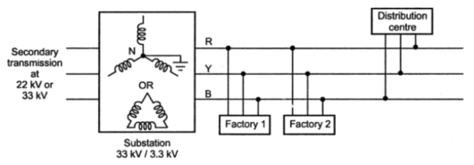
Fig. 1 Three phase three wire scheme
1.2 Three Phase Four Wire System
The fourth wire in this system is neutral and hence the transformer secondary in such system is always star connected. This system is generally preferred for the secondary distribution. The single phase loads are connected between one of the three lines and a neutral while the three phase loads can be given three phase supply directly, along with the provision of neutral for the internal distribution.
The Fig. 2 shows the three phase four wire system.
 |
Fig. 2 Three phase four wire scheme
|
The voltage between any of the lines and a neutral is 230 V while the voltage between any two lines is 400 V.
1.3 Advantages of A.C. System
1. It is possible to build up high a.c. voltage levels, using high speed a.c. generators of large capacities.
2. The cost of such a.c. generators is very low.
3. The a.c voltages can be raised or lower as per the requirement. The generated voltage levels of 11 KV, 22 KV etc. are raised upto 220 KV for transmission purpose. This is not possible in case of d.c.
4. The maintenance of a.c. substations is very easy.
5. The high voltage levels can be lowered to safe potential using step down transformers for the distribution purpose.
6. The motors running on a.c. are simple in construction, cheaper and require less attention from maintenance point of view.
7. The a.c. supply can be converted to obtain d.c. wherever required.
8. The maintenance of a.c. substations is cheaper.
9. The transforming a.c. substations are much efficient than d.c. system using rectifiers.
1.4 Disadvantages of A.C. System
1. The construction of a.c. transmission line is more complicated than a d.c. line.
2. The resistance of a.c. line is higher due to the skin effect causing more voltage drop.
3. The drop is also due to the inductance of a.c. line, causing loss of power.
4. When the line is open, the charging current flows due to the capacitance of an a.c. line which also causes loss of power continuously.
5. The copper requirement for a.c. line is more than a d.c. line.
6. The a.c. lines are more sensitive to corona than a d.c. line.
7. The problem of synchronization of alternators exists in case of a.c. system.
8. The speed of alternators in a.c. system is not economical and required to be controlled within very low limits.
D.C. Systems
Though a.c. is extensively used everywhere, there are few applications like operation of d.c. motors, batteries, charging where d.c. supply is must. It can be obtained by using rectifiers or by d.c. generators at substations.
The d.c. systems are further classified as,
1. Two wire d.c. system
2. Two wire with midpoint earthed d.c. system
3. Three wire d.c. system
1.1 Two Wire D.C. System
It consists of two wires, one positive and other negative. The positive is outgoing while the negative is return wire. The two wire d.c. system where d.c. generators are used at the generating station is shown in the Fig. 1.
Fig. 1 Scheme of two wire d.c. system
|
The symbolic representation of two wire d.c. system is shown in the Fig. 2. The various loads are connected in parallel.
 |
Fig. 2 Two wire d.c. system
|
The details like feeders, distributors and service mains are not included in the symbolic representation. The negative line is generally earthed.
It is generally used in secondary distribution system
1.2 Two Wire D.C. System with Midpoint Earthed
In this system, there are two line conductors, the one having voltage of + with respect to midpoint which is earthed while the other is at potential - with respect to midpoint. Hence the total voltage available between the two lines is 2V. No connection is taken out from the midpoint, which is earthed at the substation. The loads requiring high d.c. voltages are connected across the lines. The symbolic representation of this system is shown in the Fig. 3.
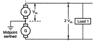 |
Fig. 3 Two wire d.c. system with midpoint earthed
|
The volume of copper required in this system is less than that required in two wire d.c. system with one line earthed.
Q- we use three wire d.c. system instead of two wire system?????
Let’s see the result for same……….
1.3 Three Wire D.C. System
This system is exactly similar to the two wire d.c. system with midpoint earthed. The only difference is, additional third wire from earth terminal of substation is available for the connections. The scheme is shown in the Fig. 4. This wire is also called neutral wire.
 |
Fig. 4 Three wire d.c. system
|
When the load is balanced, no current flows through the neutral.
Q- Why we use three wire d.c. system instead of two wire system
The loads requiring higher voltages are connected across the two outers while the loads requiring low voltages are connected between one outer and neutral as shown. so suitability with load, we use three wire d.c. system instead of two wire system.
The volume of copper required is higher than two wire midpoint earthed system but less than two wire one line earthed system.
1.4 Advantages of D.C. System
1. As the frequency of d.c. is zero, there is no inductancen or capacitance associated with the line. Hence the power losses and voltage drops are much less compared to a.c. system.
2. Due to the reduced voltage drops, the voltage regulation is better.
3. Absence of skin effect makes use of entire cross-section of conductor.
4. For the same voltage level, the voltage stress on the insulation is less in a d.c. system. Hence the insulation required in case of d.c. is less compared to a.c. system.
5. As the stress on cable insulation is less, the economical use of undeground cables is possible.
6. The stability problems as well as synchronizing difficulties are absent in a d.c. system.
7. The d.c. line has reduced interference with radio and communication circuits.
8. In a three phase a.c. system. So copper requirement is less.
1.5 Disadvantages of D.C. System
1. The power generation is not possible at high d.c. voltage levels due to commutation problems.
2. The transformer works on a.c. and not d.c. supply. So the d.c. voltage levels can not be stepped up or lowered as per the requirement. Hence transmission at high voltage is not possible. This is the biggest disadvantages of a d.c. system.
3. Obtaining a.c. from d.c. is not easy in practice.
4. The d.c. generators and motors need a lot of maintenance and their construction cost is also more than a.c. machines of same capacity.
5. The limitations of d.c. switches as well as circuit breakers cause the problems in d.c. system.
Comparison of Volume of Copper in Overhead System
The selection of a particular type of a.c. or d.c. system for the transmission and distribution is based on comparison of amount of material i.e. copper necessary for the various systems. As mentioned earlier, the maximum stress in the overhead system exists between the conductor and earth. Hence comparison of material required is done assuming the maximum voltage between any conductor and earth being the same. The assumptions made for the comparison are :
1. The power (P) transmitted by all the systems is same.
2. The distance ( l ) over which the power is transmitted is same.
3. The power loss (W) in all the systems are same.
4. The maximum voltage (Vm) exists between any conductor and the earth, in all the systems.
Based on these assumptions, let us compare the various types of systems for the volume of copper required.
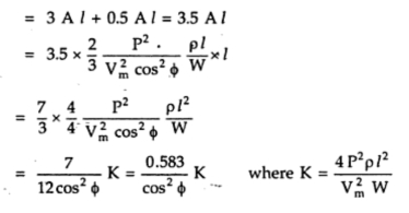
1.1 Two Wire D.C. System With One Line Earthed
The system is represented in the Fig. 1.
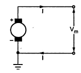 |
Fig. 1
|
The maximum voltage between the conductors is Vm, as one material is earthed.

Where P = Power transmitted
Let R = resistance of each conductor

Total copper losses in both the lines are,
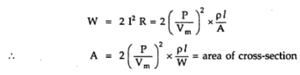
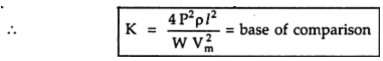
Volume of copper required is
The volume of copper required for other systems is compared by taking volume of copper required for this system as base. Let it be constant K and volume of copper required for other systems can be expressed interms of K.
1.2 Two Wire D.C. System With Midpoint Earthed
The system is represented in the Fig. 2.
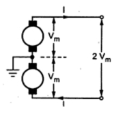 |
Fig. 2
|
As power transmitted is same as P, the current in each conductor is,

The total copper loss in both the lines is,
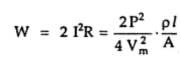
where A = area of cross-section of each line.
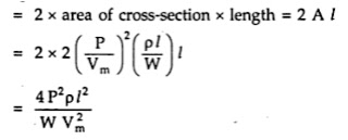
The total volume of copper required is,
Thus the volume of copper required in this system is one fourth the volume of copper required for two wire d.c. system with one line earthed.
1.3 Three Wire D.C. System
The system is represented as shown in the Fig. 3.
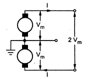 |
Fig. 3
|
When the load is balanced, current through the third neutral wire is zero.

Let A = Cross-section of outer conductors
The total copper loss is,

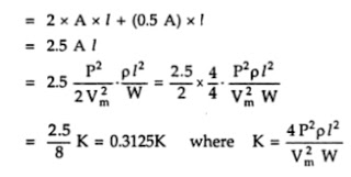
Let area of cross-section of the middle neutral wire is half of the area of cross-section of the outer conductor.
Hence the total volume of copper
= Volume of copper for outer wires + volume of copper for neutral wire
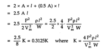
Thus the volume of copper required in this system is 0.3125 times the volume of copper required for two wire d.c. system with one line earthed.
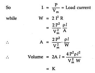
1.4 Three Phase Three Wire A.C. System
This is most commonly used system for the transmission. The three phase three wire star connected system with neutral earthed is shown in the Fig. 4.
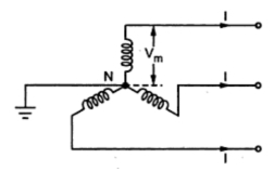 |
Fig. 4
|
The maximum voltage between each line conductor and the neutral is Vm as shown in the Fig. 4.
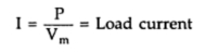
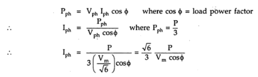
The R.M.S. value of the voltage per phase given by,

Then total power transmitted is P watts hence per phase power transmission is,

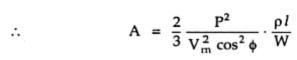
Let cosΦ be the load power factor
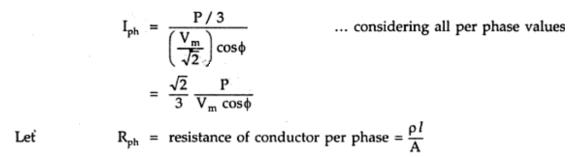
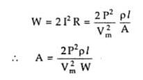
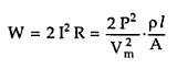
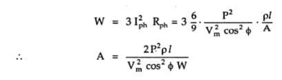
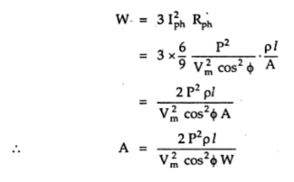
Hence the total copper loss is,
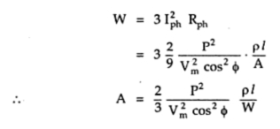
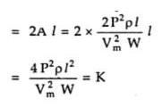
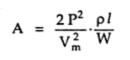
The volume of the copper required is
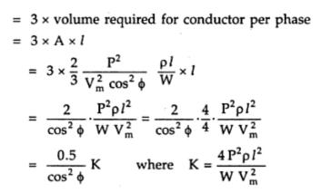
Thus the volume of copper required depends on power factor of the load and it is 0.5/cos2Φ times the volume of copper required by twp wire d.c. system with one line earthed. This system may be delta connected but irrespective of the method of connection star or delta, the result derived remains same.
1.5 Three Phase Four Wire A.C. System
This system is popularly used for secondary distribution. The neutral is also made available for the connection of the load. The system is shown in the Fig. 4.
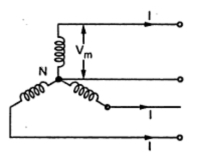 |
Fig. 5
|
Assuming the load balanced, there is no current flowing through the neutral.
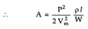
The cross-section area of neutral is half the cross-section of each conductor i.e. 0.5 A where A is cross-section of each conductor.
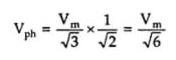
The maximum voltage between any conductor and the neutral is Vm hence r.m.s. voltage per phase is,

The power transmitted per phase is,

Hence all the calculations upto the copper losses and expression of A remain same as derived for three phase three wire system.
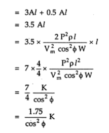
The total volume of copper requires is,
= Volume of copper for 3 lines + copper required for neutral
Thus the volume of copper required is 0.583/cos2Φ times the volume of copper required by two wire d.c. system with one line earthed.
Comparison of Volume of Copper in Underground System
In case of underground system, the maximum stress exists between the line conductors. Hence the various assumptions for such comparison are,
1. The maximum voltage (Vm), between the conductors is same.
2. The power (P) transmitted in all the systems is same.
3. The distance ( l ) over which the power is transmitted is same.
4. The copper losses (w) are same in all the systems.
1.1 Two Wire D.C. System
The system is represented in the Fig. 1.
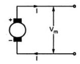 |
Fig. 1
|
The voltage between the two conductors is Vm. It can be seen that there are no changes in the condition which we have discussed for two wire D.C. system for overhead system earlier in (previous post section 1.1).
This is the base of comparison of other systems,
1.2 Two Wire D.C. System With Midpoint Earthed
The system is shown in the Fig. Fig. 2.
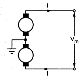 |
Fig. 2
|
it can be noted that the maximum voltage Vm exists between the two lines.

The total copper loss is,
Hence the total volume of copper required is,
Thus the volume of copper required in this system is same as that required for two wire d.c. system.
1.3 Three Wire D.C. System
The system is represented in the Fig. 3.
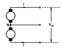 |
Fig. 3
|
Again the voltage between the two lines is maximum which is Vm.
Assume balanced load so there is no current through the neutral and there are no copper losses in neutral. So total copper loss is,
where A = area of cross-section of each line conductor.
Let area of cross-section of neutral wire is half of the area of cross-section of each conductor i.e. 0.5 A.
Hence the total volume of copper required is

Thus the volume of copper required for this system is 1.25 times that that required for 2 wire d.c. system. So 25% more copper is required in this system.
1.4 Three Phase Three Wire A.C. System
Consider a star connected three phase three wire a.c. system as shown in the Fig. 4. Note that the voltage between the line conductors is Vm. Thus the line voltage is Vm.
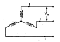 |
Fig. 4
|
The r.m.s. value of the phase voltage is,

The power transmitted per phase is,

Let cosΦ be the load power factor.

The total copper loss is,
Hence the volume of copper required is,

Thus the volume of copper required in this system depends on the load power factor and it is 1.5/cos2Φ times that that required for two wire d.c. system.
The resultant remains same whether the system is star or delta connected.
1.5 Three Phase Four Wire A.C. System
The system is shown in the Fig. 5. The neutral is available for the load connection. As the load is assumed to be balanced, the neutral current is zero and the copper losses in neutral are zero. Note that the voltage between the lines is Vm.
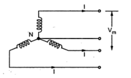 |
Fig. 5
|
Hence the r.m.s. value of the phase voltage is,
The power per phase is given by,
This is same as obtained for three phase three wire system. The total copper loss is,
Let the cross-section of the neutral wire be half of the cross-section of each line conductor i.e. 0.5 A.
Hence the total volume of copper required is
Thus the volume of copper required in this system is 1.75/cos2Φ times the volume of copper required for two wire d.c. system.
Commonly used conductor materials in overhead transmission line
The most commonly used conductor materials for over-head lines are copper, aluminium, steel-cored aluminium, galvanised steel and cadmium copper.
All conductors used for overhead lines are preferably stranded in order to increase the flexibil-ity. In stranded conductors, there is generally one central wire and round this, successive layers of wires containing 6, 12, 18, 24 ...... wires. Thus, if there are n layers, the total number of individual wires is
3n(n + 1) + 1.
Copper has high current density i.e., the current carrying capacity of copper per unit of X-sectional area is quite large. This leads to two advantages. Firstly, smaller X-sectional area of conductor is required and secondly, the area offered by the conductor to wind loads is reduced. Moreover, this metal is quite homogeneous, durable and has high scrap value.
2. Aluminium :
- The conductivity of aluminium is 60% that of copper.
- For the same resistance, the diameter of aluminium conductor is about 1·26 times the diameter of copper conductor.
- The specific gravity of aluminium (2·71 gm/cc) is lower than that of copper (8·9 gm/cc).
The steel cored aluminium conductors have the following advantages :
- The reinforcement with steel increases the tensile strength but at the same time keeps the composite conductor light. Therefore, steel cored aluminium conductors will produce smaller sag and hence longer spans can be used.
- Due to smaller sag with steel cored aluminium conductors, towers of smaller heights can be used.
No comments:
Post a Comment