Electrical drives are integral part of industrial and automation processes, particularly where precise control of speed of the motor is the prime requirement. In addition, all modern electric trains or locomotive systems have been powered by electrical drives. Robotics is another major area where adjustable speed drives offer precise speed and position control.
Even in our day-to-day lives, we can find so many applications where variable speed drives (or adjustable speed drives) have been using for fulfilling a wide range of functions including control of electric shavers, computer peripheral control, automatic operation of washing machines, and so on.
What is an Electric Drive? Why It is Needed?
A drive operates and controls the speed, torque and direction of moving objects. Drives are generally employed for speed or motion control applications such as machine tools, transportation, robots, fans, etc. The drives used for controlling electric motors are known as electrical drives.
The drives can be of constant or variable type. The constant speed drives are inefficient for variable speed operations; in such cases variable speed drives are used to operate the loads at any one of a wide range of speeds.
Why Electrical Drives are needed?
The adjustable speed drives are necessary for precise and continuous control of speed, position, or torque of different loads. Along with this major function, there are many reasons to use adjustable speed drives. Some of these include
- To achieve high efficiency: Electrical drives enable to use wide range of power, from milliwatts to megawatts for various speeds and hence the overall cost of operating the system is reduced
- To increase the speed of accuracy of stopping or reversing operations of motor
- To control the starting current
- To provide the protection
- To establish advanced control with variation of parameters like temperature, pressure, level, etc.
The advancement of power electronic devices, microprocessors and digital electronics led to the development of modern electric drives which are more compact, efficient, cheaper and have higher performance than bulky, inflexible and expensive conventional electric drive system that employs multi-machine system for producing the variable speed.
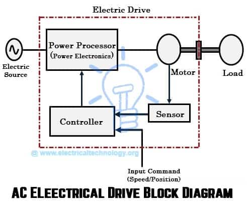
Block Diagram of an AC Electric Drive
The components of a modern electric drive system are illustrated in below figure. In the above block diagram of an electric drive system, electric motor, power processor (power electronic converter), controller, sensors (e.g PID Controller) and the actual load or apparatus are shown as the major components included in the drive.
The electric motor is the core component of an electrical drive that converts electrical energy (directed by power processor) into mechanical energy (that drives the load). The motor can be DC motor or AC motor depends on the type of load.
Power processor is also called as power modulator which is basically a power electronic converter and is responsible for controlling the power flow to the motor so as to achieve variable speed, reverse and brake operations of the motor. The power electronic converters include AC-AC, AC-DC, DC-AC and DC-DC converters.
The controller tells the power processor, how much power it has to generate by providing the reference signal to it after considering the input command and sensor inputs. The controller could be a microcontroller, a microprocessor, or a DSP processor.
A variable speed drive used to control DC motors are known as DC drives and the variable speed drives used to control AC motors are called as AC drives. In this article we are going to discuss about the AC drives.
Classification of AC Drives
AC drives are used to drive the AC motor especially three phase induction motors because these are predominant over other motors in most of the industries. In industrial terms, AC drive is also called as variable frequency drive (VFD), variable speed drive (VSD), or adjustable speed drive (ASD).
Though there are different types of VFDs (or AC drives), all of them are works on same principle that converting fixed incoming voltage and frequency into variable voltage and frequency output. The frequency of the drive determines the how fast motor should run while the combination of voltage and frequency decides the amount of torque that the motor to generate.
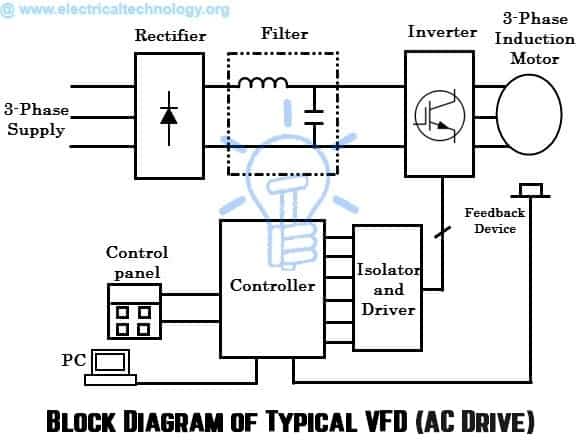
A VFD is made up of power electronic converters, filter, a central control unit (a microprocessor or microcontroller) and other sensing devices. The block diagram of a typical VFD is shown below.
Block Diagram of AC Drive (Typical VFD)
Construction and Parts of a Typical VFD AC Drive
The various sections of the variable frequency drive (VFD) include
Rectifier and Filter section converts the AC power into DC power with negligible ripples. Mostly, the rectifier section is made with diodes that produce uncontrollable DC output. The filter section then removes ripples and produces the fixed DC from pulsating DC. Depends on the type of supply number of diodes is decided in the rectifier. For example, if it is three phase supply, a minimum of 6 diodes are required and hence it is called as six pulse converter.
The inverter takes the DC power from the rectifier section and then converts back to the AC power of variable voltage and variable frequency under the control of microprocessor or microcontroller. This section is made with series of transistors, IGBTs, SCRs, or MOSFETs and these are turned ON/OFF by the signals from the controller. Depends on the turn ON of these power electronic components, the output and eventually the speed of the motor is determined.
The controller is made with microprocessor or microcontroller and it takes the input from sensor (as speed reference) and speed reference from the user and accordingly triggers the power electronic components in order to vary the frequency of the supply. It also performs overvoltage and under voltage trip, power factor correction, temperature control and PC connectivity for real time monitoring.
Principle Operation of Variable Frequency Drive (VFD)
We know that the speed of an induction motor is proportional to the frequency of the supply (N = 120f/p) and by varying the frequency we can obtain the variable speed. But, when the frequency is decreased, the torque increases and thereby motor draw a heavy current. This in turn increases the flux in the motor. Also the magnetic field may reach to the saturation level, if the voltage of the supply is not reduced.
Therefore, both the voltage and frequency have to be changed in a constant ratio in order to maintain the flux within the working range. Since the torque is proportional to the magnetic flux, the torque remains constant throughout the operating range of v/f. The above figure shows the torque and speed variation of an induction motor for voltage and frequency control. In the figure, voltage and frequency are changed at a constant ratio up to the base speed. Thus the flux and thereby torque remain almost constant up to the base speed. This region is called as a constant torque region.
Since the supply voltage can be changed up to the rated value only and hence the speed at rated voltage is the base speed. If the frequency increased, beyond the base speed, the magnetic flux in the motor decreases and thereby torque begins falling off. This is called flux weakening or constant power region.
This type of control is called constant v/f control method used in variable frequency drives (VFDs) and it is the most popular type of control in industries. Suppose the induction motor is connected to a 460V, 60Hz supply, then the ratio will be 7. 67 V/Hz (as 460/60 = 7.67). As long as this ratio maintained in proportion, the motor will develop a rated torque and variable speed.
Control Schemes of VFD
There are different speed control techniques implemented for variable frequency drives. The major classification of control techniques used in modern VFDs is given below.
- Scalar Control
- Vector Control
- Direct Torque Control
Scalar Control
In this, the magnitudes of voltage and frequency are controlled by maintaining v/f ratio constant and hence called as scalar control (scalar values determines the speed and torque). The motor is fed with variable voltage and frequency signals generated by the PWM control from an inverter.
The inverter can be controlled with a microcontroller, microprocessor, or any other digital controller depending upon the type of manufacturer. This control scheme is widely used because it requires a little knowledge of the motor to perform the speed control. The scalar control can be implemented in a number of ways and some of the popular schemes include
Sinusoidal PWM
In this method, the frequency of the switch is varied depending on the sped reference input and the average or RMS value of the voltage for that frequency is determined by number of pulses and width of the pulses. If the width of the pulse is varied, the voltage across the motor is also varied. This voltage creates the sinusoidal current through motor which is much closer to true sine wave.
Only little calculations are needed to achieve this method. However, this method has disadvantages that it includes harmonics at PWM switching speed and also the magnitude of fundamental voltage is less than 90%. In this method, sinusoidal weighted values are stored in the microcontroller or microprocessor and are made to available at the output port at user defined intervals which are then applied to the inverter in order to produce a variable supply to the motor.
Six-Step PWM
In this method, the inverter of the VFD has six distinct switching states and they are switched in a specific order so as to produce the variable voltage and frequency to the motor. The direction reversal of the motor is readily accomplished by changing the inverter output phase sequence by means of the firing angle.
This method can easily be implemented as there is no intermediate calculations are required and also the magnitude of fundamental voltage is more than the DC bus. However the low order harmonics are high in this method which cannot be filtered by the motor inductance and hence it results more losses, motor jerky operation and high torque ripple.
Space Vector Modulation PWM (SVPWM)
In this technique, three phase voltage vectors of an induction motor are converted into a single rotating vector. The inverter of the VFD can be driven to eight unique states. The PWM voltage to the load is accomplished by properly selecting the switch states of the inverter and by calculating appropriate time period for each state.
By using space vector transformation, three phase sine waves are generated for each state, which are then applied to the motor.
The main advantage of this technique is that the harmonic magnitude is less at the PWM switching frequency. However, more calculations are required for employing this technique.
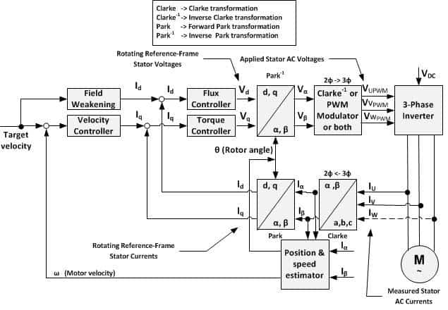
Vector Control
This method is also called flux oriented control, field oriented control, or indirect torque control. In this, three phase current vectors are converted to a two-dimensional rotating reference frame (d-q) from a three-dimensional reference frame using Clarke-Park transformation. The ‘d’ component is the flux producing component of the stator current and the ‘q’ component is the torque producing component. The two components are controlled independently through separate PI controller and then the outputs of PI controllers are transformed back to three dimensional stationary reference plane using inverse of the Clarke-Park transformation.
Using space vector modulation technique, the corresponding switching is pulse width modulated. The different types of vector control techniques include stator flux oriented control, rotor flux oriented control and magnetizing flux oriented control.
The vector control gives better torque response and accurate speed control compared to scalar control. But, it requires complex algorithm for speed calculations and it is costlier compared to scalar control due to feedback devices.
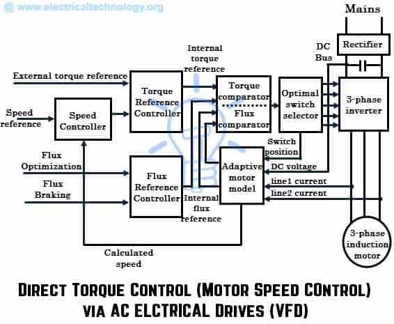
Direct Torque Control
This method has no fixed switching pattern as compared with traditional vector control. It switches the inverter according to the need of the load. This technique achieves high response particularly during changes of the load due to the absence of fixed switching pattern. It eliminates the use of any feedback, although it ensures the speed accuracy up to 0.5%. This technique uses the adaptive motor model which is based on the mathematical expressions of basic motor theory. This model requires the basic parameters of the motor such as stator resistance, saturation co-efficiency, mutual inductance, etc. and the algorithm captures this data without rotating the motor. This model calculates the actual torque and flux of the motor by considering inputs like DC bus voltage, current switch position and line currents. Then these values are given to the two level comparators of the torque and flux.
The output of the comparators is the torque and flux reference signals and is given to the switch selection table, wherein selected switch position is applied to the inverter without any modulation. Hence the name direct torque control as the motor torque and flux become direct controlled variables.
Real Time AC Drives at Glance
Several advanced features of AC drives or (VFDs) make them as a cost-effective choice in variable speed applications. The features like package designs, analog I/Os, digital I/Os, multi-functional keypads, and IGBT technology make VFDs easy to set up for any application.
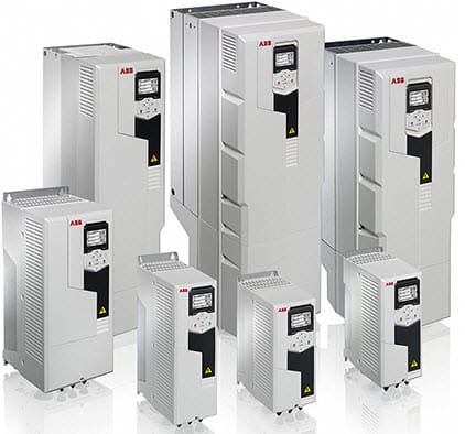
Nowadays, Most AC drive designs are of more compact, because of the use of microprocessors, IGBTs and also the use of surface mount technology ( e.g SMD Resistors) for assembling components. These units can be wall-mounted or freestanding drives. There are various drives from different manufacturers including ABB, AB, Siemens, Delta and so on. Various packages of ABB AC drives are shown below.
Basically, a setup of AC drive for an application includes three major steps, namely control wiring, power wiring and software programming. Once the power and control wiring is done, we have to configure the AC drive parameters appropriate to the application requirements through software programming, removable keypad, or remote operator panel.
There is no need of rewiring the drive, if the application is altered. The setup for new applications is performed simply by changing the drive functions in the program.
AC drives are provided with analog inputs (like speed reference), analog outputs (for auxiliary metering), digital inputs (like start, stop, reverse, etc.), and relay outputs (speed relays, fault relays, etc.) in the control wiring section. This section is monitored by dedicated software called I/O status that monitors and displays the drive inputs and outputs.
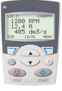
In conventional drives, programming panels or touch keypads are attached to the drive itself. Modern drives consist of removable programming panels that allow the user to program, navigate various functions and configure the drive appropriate to the application requirement.
Apart from hand tools, every AC drive comes with a dedicated software which makes easy to start up and maintenance tool. This tool consists of setup wizards for setting of parameters. The software tool allows viewing, editing, saving and downloading parameters into the drive. It also provides the graphical and numerical signal monitoring.
During the design, manufacturers programs the AC drive parameters to default values. So the operator need to load the motor data values and values to customize the drive to the application. In addition to default values, manufacturers also provide macros which are nothing but a preprogrammed set of values.
The user or operator can set up and configure all the parameters included in macros in a few seconds rather than setting all parameters individually which could take several minutes. These macros include three-wire control, hand-auto, PID control and torque control.
Proportional-integral-derivative (PID) control macro allows the drive to control the speed automatically by receiving the control inputs such as pressure, temperature, or tank level. With proper programming of analog and digital I/O parameters with PID control macro, the closed loop operation of the drive is achieved.
AC drives are built with plug-in field bus control option in order to make a connection with major automated systems like PLCs, PCs, PACs, SCADA systems, etc. They can support a wide variety of communication field bus systems including DeviceNet, PROFIBUS DP, ControlNet, MODBUS, PROFINET, Ethernet/IP, etc.


 The very basic


 Step 1:
Initially considering the armature is in its starting point or reference position where the angle α = 0.
Step 1:
Initially considering the armature is in its starting point or reference position where the angle α = 0.
 Step 2:
Once the armature is set in motion, the angle α between the actual position of the armature and its reference initial position goes on increasing in the path of its rotation until it becomes 90° from its initial position. Consequently the term cosα decreases and also the value of torque.
Step 2:
Once the armature is set in motion, the angle α between the actual position of the armature and its reference initial position goes on increasing in the path of its rotation until it becomes 90° from its initial position. Consequently the term cosα decreases and also the value of torque.

