Nowadays, computer control is one of the most cost effective solutions for improving reliability, optimum operation, intelligent control and protection of a power systemnetwork. Having advanced data collection capabilities, SCADA system plays a significant role in power system operation.
Typically, at distribution side SCADA does more than simply collecting data by automating entire distribution network and facilitating remote monitoring, coordinate, control and operating distribution components just like in Smart Grid System.

Before knowing distribution automation using SCADA, let us look at what exactly SCADA is and its functioning and what they do in the distribution system.
What is SCADA?
Supervisory Control and Data Acquisition or simply SCADA is one of the solutions available for data acquisition, monitor and control systems covering large geographical areas. It refers to the combination of data acquisition and telemetry.
SCADA systems are mainly used for the implementation of monitoring and control system of an equipment or a plant in several industries like power plants, oil and gas refining, water and waste control, telecommunications, etc.

In this system, measurements are made under field or process level in a plant by number of remote terminal units and then data are transferred to the SCADA central host computer so that more complete process or manufacturing information can be provided remotely.
This system displays the received data on number of operator screens and conveys back the necessary control actions to the remote terminal units in process plant.
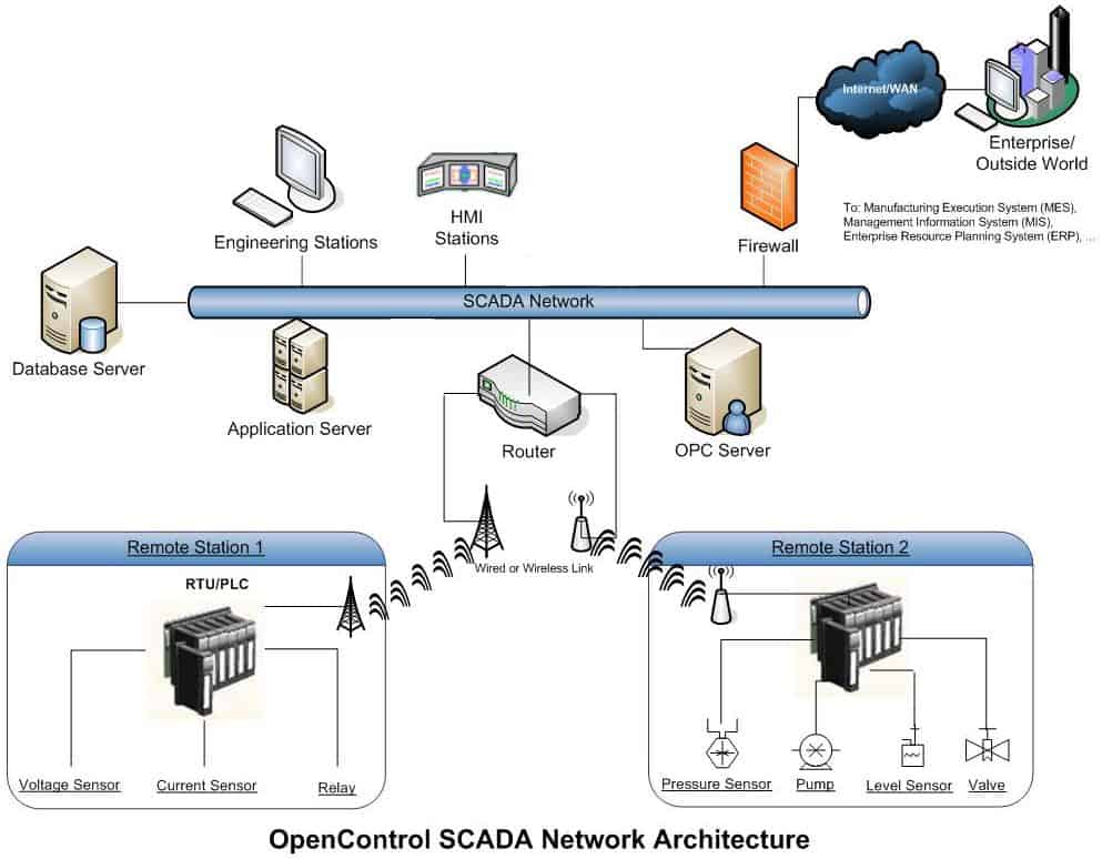
Components of Typical SCADA System
The major components in SCADA system are
Remote Terminal Units (RTUs)
RTU is the main component in SCADA system that has a direct connection with various sensors, meters and actuators associated with a control environment.
These RTUs are nothing but real-time programmable logic controllers (PLCs) which are responsible for properly converting remote station information to digital form for modem to transmit the data and also converts the received signals from master unit in order to control the process equipment through actuators and switchboxes.
Master Terminal Units (MTUs)
A central host servers or server is called Master Terminal Unit, sometimes it is also called as SCADA center. It communicates with several RTUs by performing reading and writing operations during scheduled scanning. In addition, it performs control, alarming, networking with other nodes, etc.
Communications System
The communication network transfers data among central host computer servers and the field data interface devices & control units. The medium of transfer can be cable, radio, telephone, satellite, etc. or any combination of these.
Operator Workstations
These are the computer terminals consisting of standard HMI (Human Machine Interface) software and are networked with a central host computer. These workstations are operator terminals that request and send the information to host client computer in order to monitor and control the remote field parameters.
Automation of Electrical Distribution System
Modern SCADA systems replace the manual labor to perform electrical distribution tasks and manual processes in distribution systems with automated equipments. SCADA maximizes the efficiency of power distribution system by providing the features like real-time view into the operations, data trending and logging, maintaining desired voltages, currents and power factors, generating alarms, etc.
SCADA performs automatic monitoring, protecting and controlling of various equipments in distribution systems with the use of Intelligent Electronic Devices (or RTUs). It restores the power service during fault condition and also maintains the desired operating conditions.
SCADA improves the reliability of supply by reducing duration of outages and also gives the cost-effective operation of distribution system. Therefore, distribution SCADA supervises the entire electrical distribution system. The major functions of SCADA can be categorized into following types.
- Substation Control
- Feeder Control
- End User Load Control
Also read: Fault Current Limiter and Their Types
Substation Control using SCADA
In substation automation system, SCADA performs the operations like bus voltage control, bus load balancing, circulating current control, overload control, transformer fault protection, bus fault protection, etc.
SCADA system continuously monitors the status of various equipments in substation and accordingly sends control signals to the remote control equipments. Also, it collects the historical data of the substation and generates the alarms in the event of electrical accidents or faults.
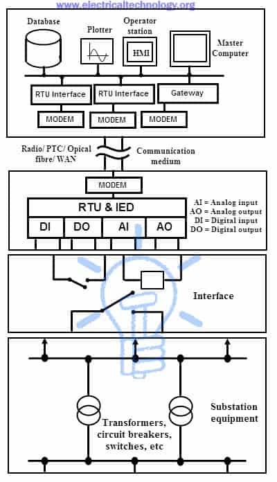
The above figure shows the typical SCADA based substation control system. Various input/output (I/O) modules connected to the substation equipment gathers the field parameters data, including status of switches, circuit breakers, transformers, capacitors and batteries, voltage and current magnitudes, etc. RTUs collect I/O data and transfers to remote master unit via network interface modules.
The central control or master unit receives and logs the information, displays on HMI and generate the control actions based on received data. This central controller also responsible for generating trend analysis, centralized alarming, and reporting.
The data historian, workstations, master terminal unit and communications servers are connected by LAN at the control center. A Wide Area Network (WAN) connection with standard protocol communication is used to transfer the information between field sites and central controller.
Thus, by implementing SCADA for substation control eventually improves the reliability of the network and minimizes the downtime with high speed transfer of measurements and control commands.
Feeder Control using SCADA
This automation includes feeder voltage or VAR control and feeder automatic switching. Feeder voltage control performs voltage regulation and capacitor placement operations while feeder switching deals with remote switching of various feeders, detection of faults, identifying fault location, isolating operation and restoration of service.
In this system, SCADA architecture continuously checks the faults and their location by using wireless fault detector units deployed at various feeding stations. In addition, it facilitates the remote circuit switching and historical data collection of feeder parameters and their status. The figure below illustrates feeder automation using SCADA.

In the above typical SCADA network, different feeders (underground as well as overhead networks) are automated with modular and integrated devices in order to decrease the number and duration of outages. Underground and overhead fault detection devices provide accurate information about transient and permanent faults so that at the remote side preventive and corrective measures can be performed in order to reduce the fault repeatability.
Ring main units and Remote Control Units (RTUs) of underground and overhead network responsible for maintenance and operational duties such as remote load switching, capacitor bank insertion and voltage regulation. The entire network is connected with a communication medium in order to facilitate remote energy management at the central monitoring station.
End User Load Control Automation by SCADA
This type of automation at user end side implements functions like remote load control, automatic meter reading and billing generation, etc. It provides the energy consumption by the large consumers and appropriate pricing on demand or time slots wise. Also detects energy meter tampering and theft and accordingly disconnects the remote service. Once the problem is resolved, it reconnects the service.

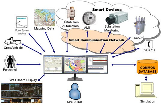
The above figure shows a centralized meter data-management system using SCADA. It is an easy and cost-effective solution for automating the energy meter data for billing purpose.
In this, smart meters with a communication unit extract the energy consumption information and made it available to a central control room as well as local data storage unit. At the central control room, AMR control unit automatically retrieves, stores and converts all meter data.
Modems or communication devices at each meter provide secure two-waycommunication between central control and monitoring room and remote sites.
Advantages of Implementing SCADA systems for Electrical Distribution
- Due to timely recognition of faults, equipment damage can be avoided
- Continuous monitoring and control of distribution network is performed from remote locations
- Saves labor cost by eliminating manual operation of distribution equipment
- Reduce the outage time by a system-wide monitoring and generating alarms so as to address problems quickly
- Improves the continuity of service by restoring service after the occurrence of faults (temporary)
- Automatically improves the voltage profile by power factor correction and VAR control
- Facilitates the view of historian data in various ways
- Reduces the labor cost by reducing the staff required for meter reading


